 A
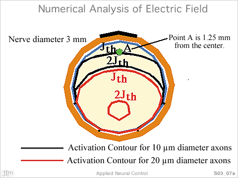
reference point ‘A’ was located midway between
the center of the nerve and the center of the cathode (1.25
mm radially from the center). The driving function at point
A due to a stimulus of –1 V at the cathode was calculated.
The threshold current density was determined to be 4.88 mA/sq.
cm.
A
reference point ‘A’ was located midway between
the center of the nerve and the center of the cathode (1.25
mm radially from the center). The driving function at point
A due to a stimulus of –1 V at the cathode was calculated.
The threshold current density was determined to be 4.88 mA/sq.
cm.
V thr (A/10µm) was defined to be the threshold voltage
stimulus required to activate a 10 µm axon at point
A and was calculated by scaling –1 Volt, with the ratio
of 4.88 mA/sq.cm. to the driving function DF(i). If the value
of the driving function for a 10 µm diameter axon at
location ‘A’ was half of threshold with a stimulus
of V volts, then a stimulus of 2V volts would be needed to
activate the axon.
The threshold stimulus was found to be lowest at nodes of Ranvier in the X-Y
plane passing through the center of the cathode. Finite element solutions were
found for stimulus of –1 V at the cathode. In the figure, equivalent driving
function DF (i) contours for threshold current density of 4.88 mA/sq. cm (J)
and for 2.44 mA/sq. cm (2J) are shown for 10 µm and 20 µm axons.
All the axons of a particular diameter are activated in the region between the
Jth contour line and the nerve surface towards the electrode. A voltage of twice
threshold is required to activate fibers in the region between contour lines
2Jth and the surface of the nerve towards the electrode.
[1] Chintalacharuvu, R., Ksienski, D., & J.T. Mortimer (1991) A numerical
analysis of the electric field generated by a nerve cuff electrode. Proc. of
the IEEE-Eng. Med. Biol. Soc. 13th Ann. Conf., 13(2), 912-913.
and Chintalacharuvu, Rekha Rani, (1991)“A numerical analysis of the electric
field generated by the nerve cuff electrode”, MS Thesis, Dept of Electrical
Engineering and Applied Physics, Case Western Reserve University, Cleveland,
OH, USA.
[2] McNeal, D.R. (1976) Analysis of a model for excitation of myelinated nerve.
IEEE Trans. Biomed. Engg. Vol.23, pp 329 – 337.
[3] Warman, E., Grill, W. & D. Durand (1999) Modeling the effects of electric
fields on nerve fibers: Estimation of excitation. IEEE Trans. Biomed. Engg.
[4] Sweeney, J.D., Mortimer, J.T. & D. Durand (1987) Modelling of mammalian
myelinated nerves for functional neuromuscular stimulation. Proc. 9th. Ann. Conf.
IEEE-EBMS. pp. 1578 – 1579.

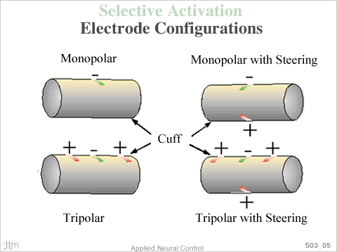 The
four electrode configurations modeled are shown in the figure.
The monopolar configuration considered a single cathodic
contact in the x-y [plane of symmetry at the center of the
nerve cuff. The monopolar with steering configuration added
an anodic contact placed radially 180 degrees opposite to
the cathodic contact.
The
four electrode configurations modeled are shown in the figure.
The monopolar configuration considered a single cathodic
contact in the x-y [plane of symmetry at the center of the
nerve cuff. The monopolar with steering configuration added
an anodic contact placed radially 180 degrees opposite to
the cathodic contact. 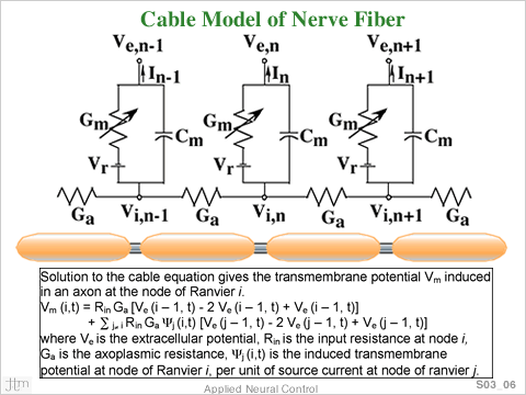 A
cable model of myelinated axons by McNeal [2] was used for
analysis of the electric field from the electrode. An equivalent
driving function, as defined by Warmen et al. [3] was used
to predict axon excitation. The solution to the cable equation
gave the transmembrane potential Vm induced at a node of
Ranvier.
A
cable model of myelinated axons by McNeal [2] was used for
analysis of the electric field from the electrode. An equivalent
driving function, as defined by Warmen et al. [3] was used
to predict axon excitation. The solution to the cable equation
gave the transmembrane potential Vm induced at a node of
Ranvier.