| |
|
|
|
|
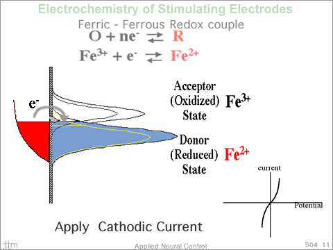
 By
increasing the electron energy in the metal, raising the
Fermi level above E0, electrons can be transferred to the
acceptor, creating more ions in the reduced state and decreasing
the number in the oxidized state. Similarly, by lowering
the Fermi level in the electrode, electrons, from ions in
the reduced state, can be transferred to the electrode. The
potential displacement from E0 is termed the overpotential.
When the Fermi level of the electrode is displace from equilibrium
by the application of an outside potential source, current
begins to flow in the circuit, electron transfer occurs at
the interface. The current flowing into the electrode, when
plotted as a function of potential displacement from equilibrium,
would yield a plot as shown here. By
increasing the electron energy in the metal, raising the
Fermi level above E0, electrons can be transferred to the
acceptor, creating more ions in the reduced state and decreasing
the number in the oxidized state. Similarly, by lowering
the Fermi level in the electrode, electrons, from ions in
the reduced state, can be transferred to the electrode. The
potential displacement from E0 is termed the overpotential.
When the Fermi level of the electrode is displace from equilibrium
by the application of an outside potential source, current
begins to flow in the circuit, electron transfer occurs at
the interface. The current flowing into the electrode, when
plotted as a function of potential displacement from equilibrium,
would yield a plot as shown here.
|
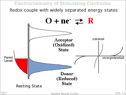
 Now
consider a redox couple where the density of states, describing
the acceptor state and that describing the donor state, are
widely separated. The large separation between the densities
of states is a characteristic of an irreversible reaction.
Assuming that the concentration of the two forms of the species
are equal, an electrode immersed in an aqueous solution containing
this redox couple would assume a potential E0, half way between
the two density of state representations. As the potential
of the immersed electrode is made more negative, Fermi level
raised, no electron transfer occurs until the Fermi level
of the electrode begins to overlap the acceptor density of
states. A similar situation occurs when the electrode is
made more positive. Over the potential region where electron
transfer does not occur, charge is moved onto the electrode/electrolyte
interface, double layer charging. When the electrode is made
more negative, negative charge is added to the metal and
positive charge is moved closer to the electrode in the electrolyte
medium. The opposite occurs when the electrode potential
is made positive, when an anodic current is applied. Potential
excursions in the region were electron transfer does not
occur are treated as charging and discharging a capacitor
and are is modeled as capacitor. A typical value for double
layer capacitance is ~20µF/cm2. The current flowing
in the circuit is a combination of double layer capacitance
current, if the potential at the interface is changing as
a function of time, and electron transfer across the interface.
Plotting the current flowing in the electrode circuit, as
a function of interface potential, is shown in the figure.
The currents are similar to the previous case except that
the onset of current flow occurs at greater potential values.
Since capacitive current is very small in this representation,
the sweep rate, dV/dt, must be small. Now
consider a redox couple where the density of states, describing
the acceptor state and that describing the donor state, are
widely separated. The large separation between the densities
of states is a characteristic of an irreversible reaction.
Assuming that the concentration of the two forms of the species
are equal, an electrode immersed in an aqueous solution containing
this redox couple would assume a potential E0, half way between
the two density of state representations. As the potential
of the immersed electrode is made more negative, Fermi level
raised, no electron transfer occurs until the Fermi level
of the electrode begins to overlap the acceptor density of
states. A similar situation occurs when the electrode is
made more positive. Over the potential region where electron
transfer does not occur, charge is moved onto the electrode/electrolyte
interface, double layer charging. When the electrode is made
more negative, negative charge is added to the metal and
positive charge is moved closer to the electrode in the electrolyte
medium. The opposite occurs when the electrode potential
is made positive, when an anodic current is applied. Potential
excursions in the region were electron transfer does not
occur are treated as charging and discharging a capacitor
and are is modeled as capacitor. A typical value for double
layer capacitance is ~20µF/cm2. The current flowing
in the circuit is a combination of double layer capacitance
current, if the potential at the interface is changing as
a function of time, and electron transfer across the interface.
Plotting the current flowing in the electrode circuit, as
a function of interface potential, is shown in the figure.
The currents are similar to the previous case except that
the onset of current flow occurs at greater potential values.
Since capacitive current is very small in this representation,
the sweep rate, dV/dt, must be small.
|
Current injected into a tissue medium is derived from capacitive
currents that result from double layer charging and from electron
transfer between the stimulating electrode and molecular species
in the electrolyte medium. For electron transfer to take place,
molecules in the medium must either accept electrons from the
electrode or donate electrons to the electrode. Radiationless
electron transfer requires that the energy level of the electron
be the same in the metal and molecular structure. Energy levels
for the reactant molecules are fixed, where as the electron
energy levels for the metal electrode can be raised or lowered
by charging and discharging the electrode with an external
power source. When the electrode potential is changing as a
function of time and no electron transfer is taking place the
current flowing in the tissue medium is due to ion migration
in response to charging and discharging the double layer.
|
|
|
|
|
|
|
|

