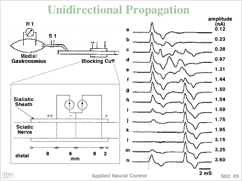
 A
tripolar nerve cuff applied around a nerve trunk can be used
to initiate action potentials (AP) under a central 'cathodic'
contact, while arresting AP propagation by a flanking 'anode'.
By making one anode carry more current than the other or
spacing the escape anode further from the centrally placed
cathode, the AP can be arrested at the end carrying the greater
current while the other allows the AP to escape. A shorter
anode to cathode distance on the left (towards the medial
Gastrocnemius muscle) lowers the electrical resistance and
allows more current to flow through that anode. This acts
as the arresting end of the electrode. The other end of the
electrode allows the propagating APs to continue travel.
This can ensure arrest of the bidirectionally propagating
AP at one end, allowing 'escape' at the other. A
tripolar nerve cuff applied around a nerve trunk can be used
to initiate action potentials (AP) under a central 'cathodic'
contact, while arresting AP propagation by a flanking 'anode'.
By making one anode carry more current than the other or
spacing the escape anode further from the centrally placed
cathode, the AP can be arrested at the end carrying the greater
current while the other allows the AP to escape. A shorter
anode to cathode distance on the left (towards the medial
Gastrocnemius muscle) lowers the electrical resistance and
allows more current to flow through that anode. This acts
as the arresting end of the electrode. The other end of the
electrode allows the propagating APs to continue travel.
This can ensure arrest of the bidirectionally propagating
AP at one end, allowing 'escape' at the other.
Experimental preparation is shown on top left of Figure. R1 is the electromyogram
recording site and S1 hook electrode for stimulation. In the bottom, left part
of the figure is a detail of an insulated tripolar electrode, shown above as
the 'Blocking Cuff'. The dashed lines on the Sciatic nerve represent ring contacts
around the nerve inside the insulating silicone rubber sheath. The applied current
is unequally divided to the two flanking contacts by using separate stimulators.
In the right side of figure is shown the Medial Gastrocnemius EMG responses to
8 mS square pulses applied through the cuff electrode, with the central contact
as the Cathode. There are two distinct responses, a short latency response, which
is presumed to have been initiated at the cathode, and the long latency compound
AP, which is presumed to have been initiated by an “anodic break” response
arising from the left most anode (designated ++) because it is highly correlated
with the lagging edge of the 8 ms current pulse. In (a) maximum EMG response
at 0.12 mA. In (b to f) growth and then decline of asynchronous activity. (f
and g) appearance of post stimulus anodic break response. (h to l) decline and
disappearance of direct response (initial deflections) at 1.95 to 3.15 mA. In
(k) and (l) a unidirectionally propagating AP, initiated at the cathode, is presumed
to have occurred. In(m and n) reappearance of the direct response at higher current
amplitudes, but at a slightly shorter latency, presumably arising from a virtual
cathode located to the left of the electrode. The “anodic break” response
can be eliminated by making the tailing edge of the stimulus pulse decay exponentially.
van den Honert, C. and J. T. Mortimer (1981). “A technique for collision
block of peripheral nerve: single stimulus analysis.” IEEE Trans
Biomed Engg. 28(5): 373-8. |

