Unlike other NSLS-II beamlines that have both a first optical enclosure (FOE) hutch and one or more experimental hutches, XFP has only a single hutch that does double duty as an FOE and experimental hutch. Following passage through the accelerator shield wall into the hutch, X-ray beam enters what we term the XFP photon delivery system (PDS, Figure 1). This system contains components to shape and monitor the X-ray beam before it exits the vacuum chamber and reaches the sample. The first element is a set of water-cooled pink beam slits (Figure 2 shows an internal view), which enable shaping of the focused beam after the FE mirror and can block extraneous scatter. The second component of the XFP PDS is an in-vacuum diamond BPM developed by Sydor Technologies as a prototype device for monitoring high-power synchrotron X-ray beams. Using four instrumented diamond sensors in a quadrant arrangement, it provides a live measure of absolute beam intensity and stability (Figure 4 shows the user interface), allowing beamline staff and users to monitor changes in beam position that could affect experimental results. Following the BPM, a pneumatic shutter built around a water-cooled tungsten block (Figure 5) allows beam to be blocked from hitting the sample; this is useful, for instance, when adjusting sample position or monitoring the BPM. Finally, the beamline terminates in a 100μm thick, 10mm wide, optically clear diamond exit window (Figure 6). This window is indirectly cooled by a cooling loop in contact with the window flange, and is purged with inert gas (either helium or nitrogen) to minimize ozone buildup that can etch the diamond and cause a vacuum leak.
For additional details, see our paper describing the design and performance of the XFP beamline (Asuru et al., J. Synch. Rad. 2019, 26, 1388-1399. DOI: 10.1107/S1600577519003576).

Figure 1. Overview of the photon delivery system for XFP in the experimental hutch (image credit: Brookhaven National Laboratory). A vacuum gate valve separates beamline vacuum from the front end, and is followed by a set of beam-defining pink beam slits, a BPM chamber that contains diagnostics, and a sample shutter for sample protection.
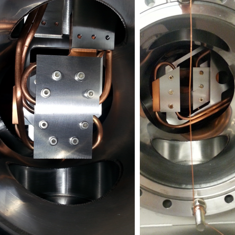
Figure 2. Internal view of the pink beam X-Y slit blade assemblies with the (closed) vertical slits on the left and (partially open) horizontal slits on the right. These water-cooled slits, the first beam defining aperture after the shield wall, were designed by Oxford Danfysik and were repurposed from the NSLS X6B beamline.
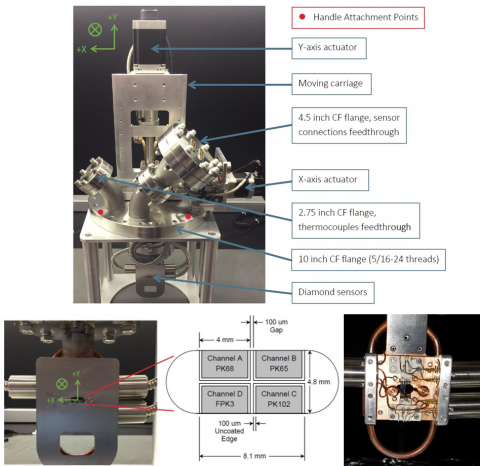
Figure 3. XFP UHV diamond beam position monitor (DBPM), built by Sydor Instruments. At top, an overview of the system showing instrumentation feedthroughs and X-Y position actuators. The bottom shows the layout of the four individual 50 micron-thick diamond sensors tiled in a quadrant arrangement. The water cooled sensor assembly is protected with a molybdenum mask and is instrumented with thermocouples for remote temperature monitoring.
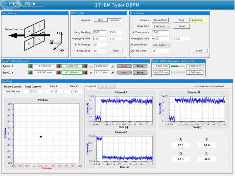
Figure 4. User interface for interaction with the XFP Sydor DBPM, with panels showing the layout of the BPM, access to controls for motorized positioning of the device, and lastly a live readback of beam intensity on each functional channel, as well as a calculated beam X-Y position that indicates beam motion or drifts.
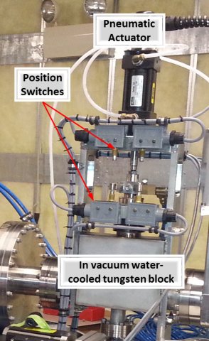
Figure 5. View of the sample pre-shutter (repurposed from NSLS X6B) taken during beamline construction. This shutter consists of an in-vacuum water-cooled tungsten block that is operated by a pneumatic actuator, with position switches to indicate its location. It is used to protect against unwanted sample exposure during translation movements, as well as stop beam during BPM or pink beam slit adjustments.
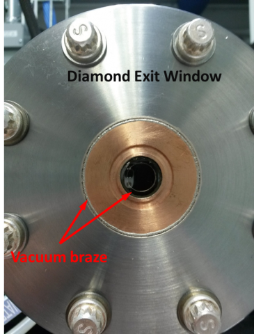
Figure 6. Diamond exit window that separates beamline vacuum from the endstations. The opening consists of a 100μm thick, 10mm wide clear diamond brazed to copper, which is in turn brazed to the stainless steel flange to provide a vacuum-tight seal.