The front end of the XFP beamline safely transports X-ray radiation from the NSLS-II storage ring to the main experimental hutch of the beamline located outside the accelerator enclosure. XFP accepts 3.0 mrad x 0.33 mrad (horizontal x vertical) of X-ray radiation from a three-pole wiggler (3PW) source (critical energy = 6.8 keV). X-ray beam can be blocked from entering the front-end by a water-cooled photon shutter. Downstream of this photon shutter, a 250 μm thick beryllium window separates storage ring vacuum from beamline vacuum. A set of water-cooled white beam slits (Figure 1) represent the first beam defining element in the beamline. These slits are current isolated to allow a diagnostic measure of beam position.
The major optical element of the beamline is a toroidal focusing mirror located 14m downstream of the 3PW source (Figures 2 and 3). This water-cooled optic consists of a 1.1m x 0.1m (LxW) Rh-coated mirror at a mixed 4.2 mrad angle (this coating and angle defines the 4.5-16 keV energy range of XFP). It provides vertical collimation and horizontal focusing of the beam, and can be bent along the longitudinal axis to a toroid for vertical focusing. The mirror assembly is fully motorized for remote alignment, with vertical and horizontal translation motions, angular adjustment of pitch, yaw, and roll, and a motorized bender motion.
After the mirror, a pneumatically actuated diagnostic beam viewer is available (Figure 4). This device permits imaging of the upward reflected beam coming off the mirror using a phosphor coated copper block, and was essential in the initial alignment of the mirror during the commissioning of XFP. A second photon shutter stops beam from passing through the shield wall into the experimental hutch when users need to change samples. In addition, a pair of lead brick-based safety shutters (Figure 5) will block Bremsstrahlung radiation from passing into the experimental hutch when the photon shutter is closed.
For additional details, see our paper describing the design and performance of the XFP beamline (Asuru et al., J. Synch. Rad. 2019, 26, 1388-1399. DOI: 10.1107/S1600577519003576).
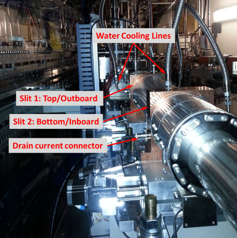
Figure 1. Water-cooled front-end slits upstream of the focusing mirror. There are two separate slit assemblies, for the top/outboard slits and the bottom/inboard slits, respectively. Both have integrated connectors for water cooling and drain current (the latter senses X-ray beam position).
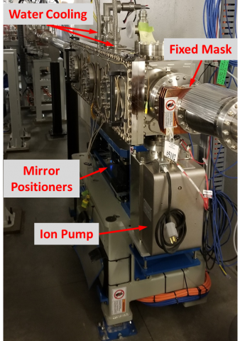
Figure 2. XFP front-end focusing mirror assembly, placed 14m downstream from the 3PW source. The assembly contains a series of motorized mirror positioners below the chamber, with an ion pump on the downstream end providing for UHV, as well as water cooling lines entering the vacuum chamber. A fixed mask downstream of the mirror protects against missteered beam.
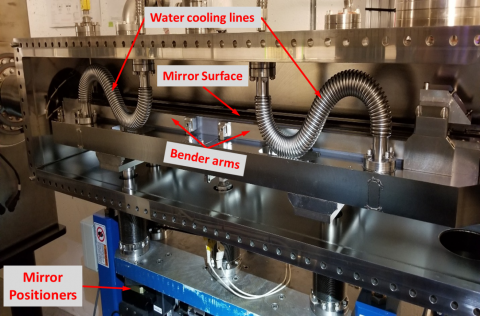
Figure 3. Interior of the XFP front-end focusing mirror chamber during its installation, showing the bender arms that bend the mirror along the longitudinal axis, as well as water cooling lines feeding into a bathtub that is in thermal contact with the mirror substrate.
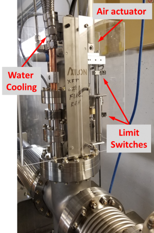
Figure 4. Diagnostic beam viewer used during XFP commissioning to align beam. The viewer comprises a water-cooled copper block 45° to the beam that is coated with a ceramic phosphor coating, that is positioned using an air actuator and limit switches for position sensing. A GigE machine vision camera on the bottom of the cross views the phosphor.
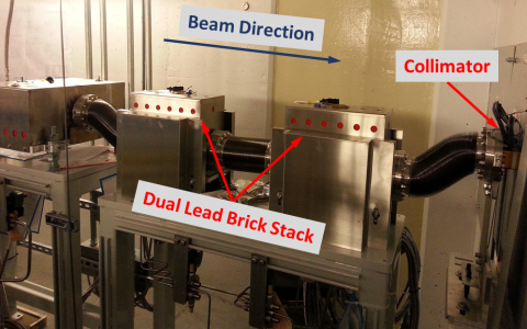
Figure 5. XFP front-end safety shutters during beamline construction. These are a redundant dual pair of lead brick stacks that block Bremsstrahlung radiation from passing through the ratchet wall collimator in order to allow personnel access to the beamline hutch.